Table of Contents
Previous: Lab 1B
Lab Tasks
Set up the IMU
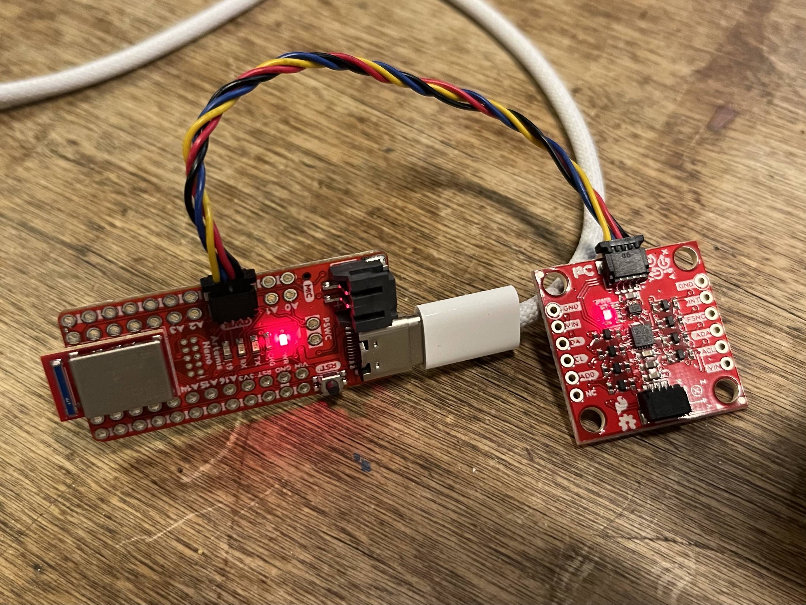
The serial output of the example code given is as shown:
We set AD0_VAL to 1 to define the I2C address of the IMU. In this case, it maintains the default address of 0x12.
Accelerometer
The accelerometer seems to be accurate and responsive to angle changes, but not at all precise.
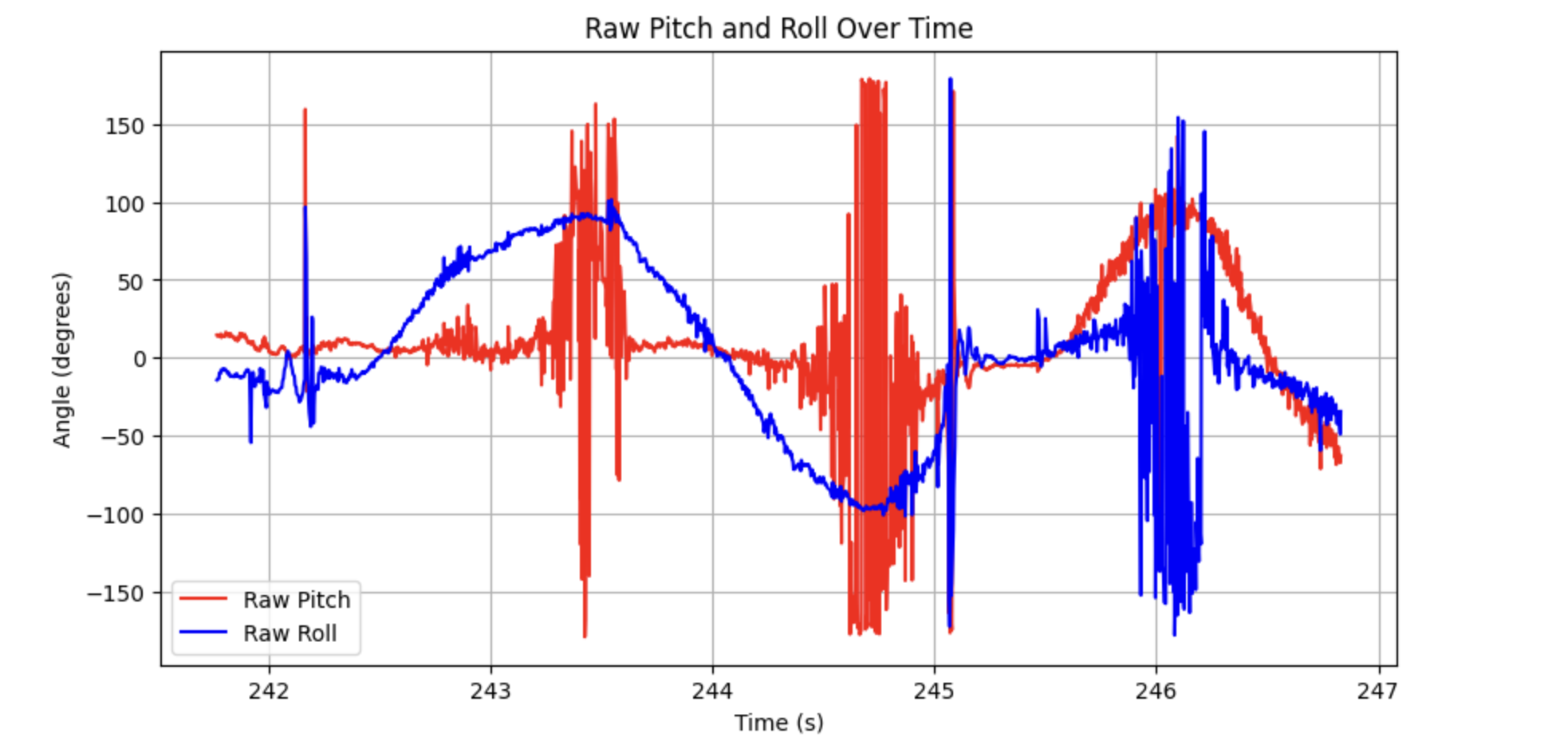
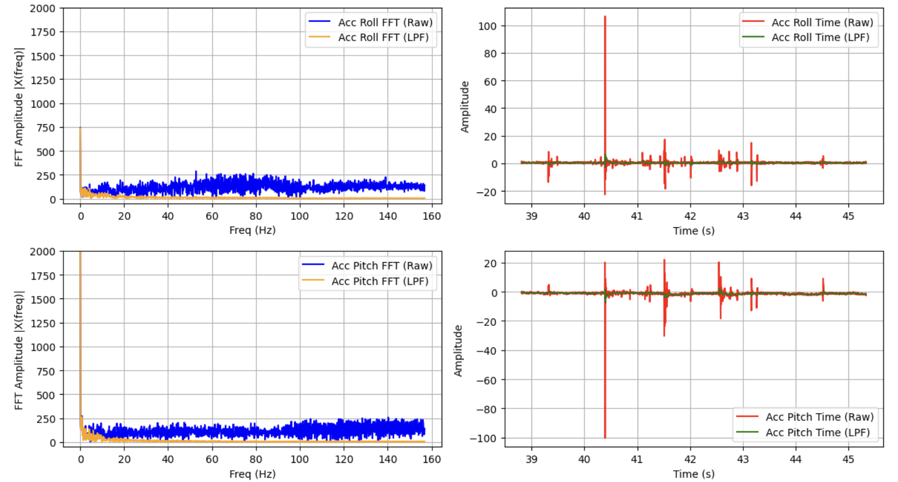
The accelerometer is very noisy, and becomes less accurate as pitch and roll tend to 90 degrees. This is because when either the pitch or roll axes approach the gravitational acceleration vector, the accelerometer is no longer able to read rotation data about that axis. I found the following noise spectrum when running the car nearby the IMU.
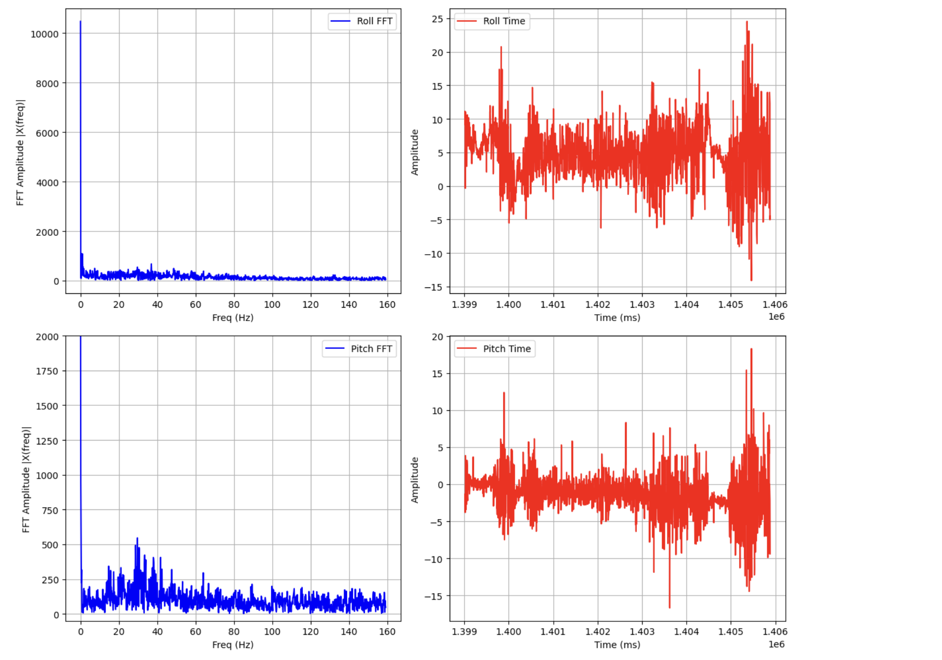
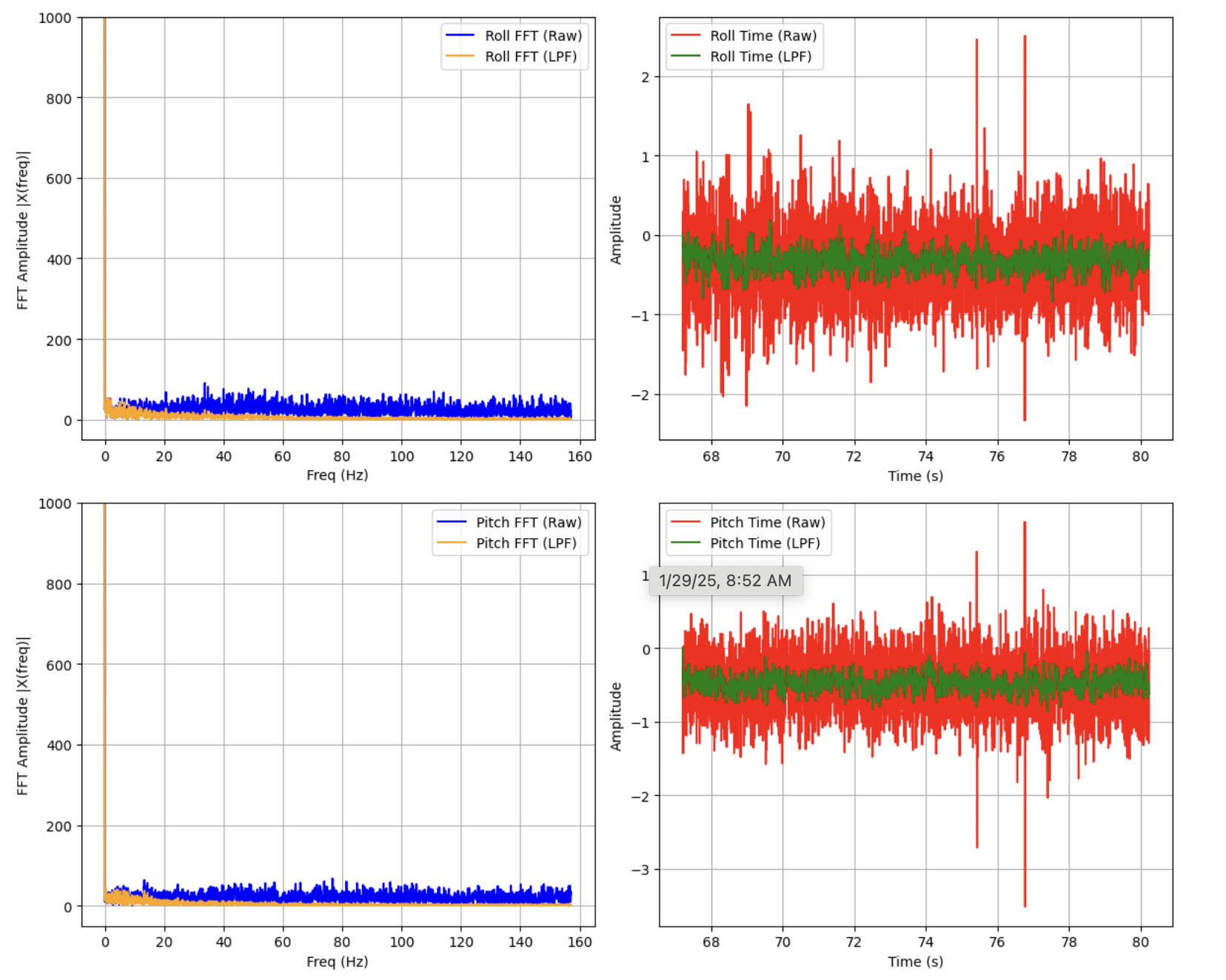
With strong noise peaks above 10 Hz, especially in pitch, a cutoff frequency of 10 Hz seemed reasonable for my calculation of $\alpha$. We first found $RC$ and substituted to find $\alpha$ using the equations $$ f_c = \frac{1}{2\pi RC} $$ $$ \alpha = \frac{T_s}{T_s + RC} $$
Where $T_s$ is the sampling period of the IMU, given in seconds. For the given noise spectrum, I calculated $\alpha = .077$, producing the following low-pass-filtered car noise and ringdown readings.
Gyroscope
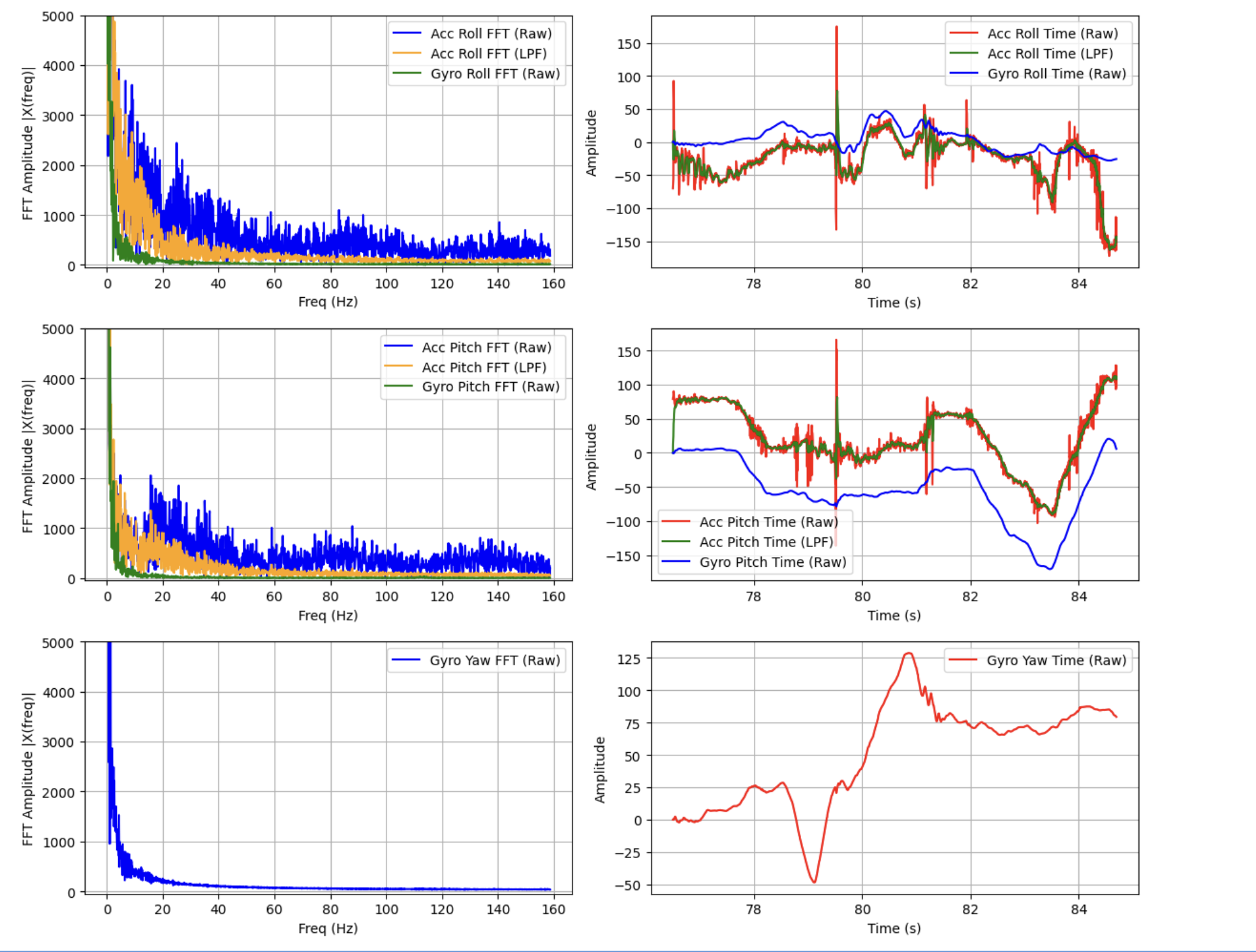
The accelerometer roughly tracked the changes in pitch, roll, and yaw expected from movement of the IMU and accelerometer readings, but struggled with the angle offset due to lack of initial conditions in the integrator. I also saw significant integrated error, especially in yaw. When the Artemis was kept static about the accelerometer and gyroscope z axis, yaw appeared to vary linearly.
With the complementary filter in place (in this case with $\alpha=.08$, similar to the pitch and roll LPF), pitch and roll values appeared to track the actual motion of the IMU much more closely, and lacked the high-frequency noise present even in the LPF accelerometer readings.
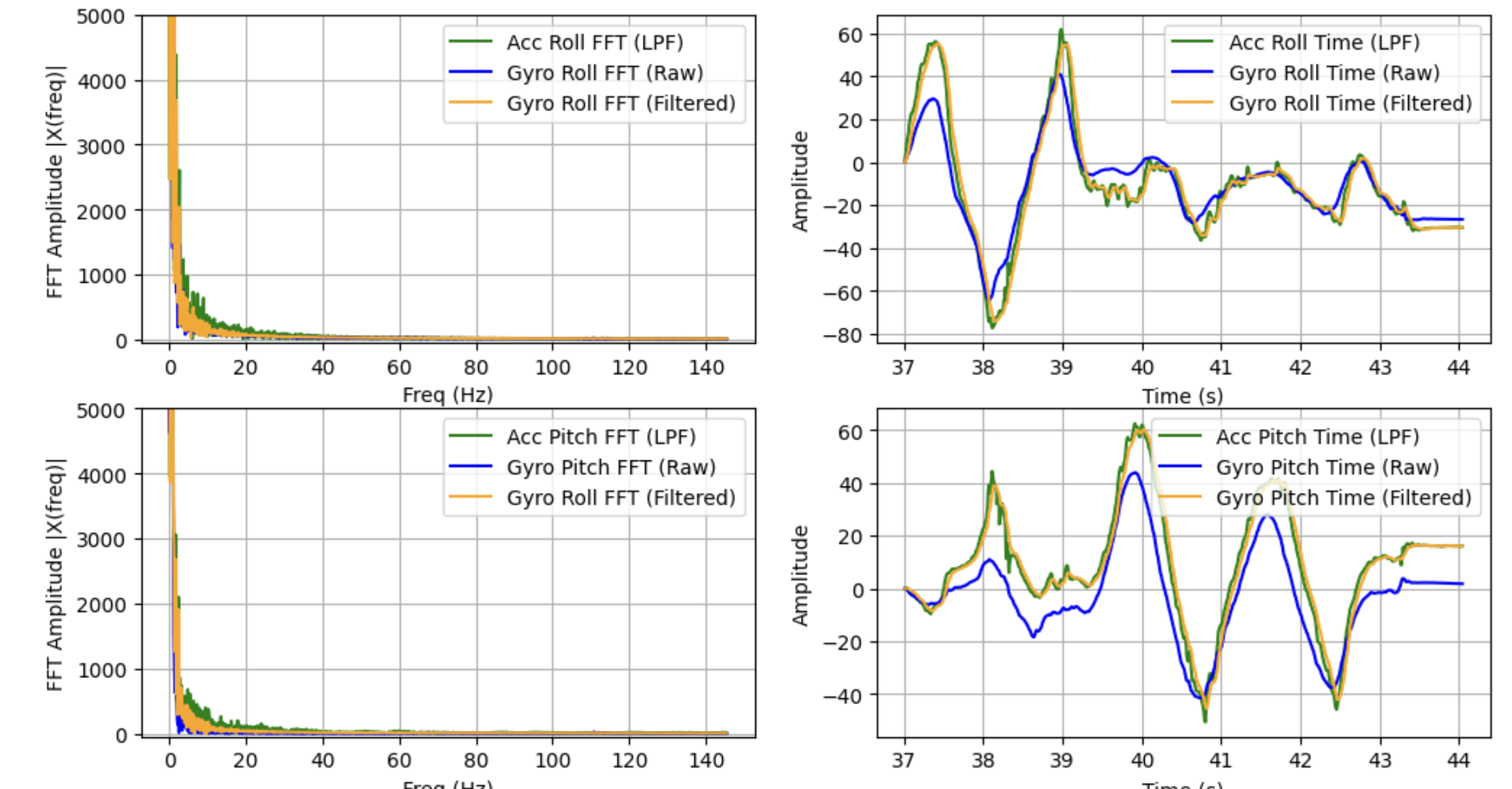
Yaw remained unfiltered as there is no accelerometer data to complement it.
Sample Data
With serial monitor prints removed, the IMU sampled at approximately 300 Hz. I found that, over a 5 sceond period, the main loop ran 3573921 times and only stored 1538 values. This means that the IMU is definitely bottlenecking our data recording.
I chose 2D arrays for each data set (e.g. filtered accelerometer, raw gyro) because it made my code more organized. However, it's slightly more difficult to determine whether pitch, roll, and yaw are being indexed for a particular data set. There may be slight performance benefits for using 2D arrays over multiple 1D arrays due to locality, but I was unable to measure any difference in this use case.
At each time step, the Artemis records the following data, as shown above:
- time (one int)
- raw accelerometer (two floats)
- filtered accelerometer (two floats)
- raw gyroscope (three floats)
- filtered gyroscope (three floats)
This means a total of 44 bytes are being stored at a time, so, assuming the 350kB of dynamic memory available as in lab 1B, we can store just under 8000 time steps. For an average measured sample rate of 300 Hz, this gives us around 27 seconds of IMU data recording.
The above plots show well over 5 seconds of data transmitted by BLE.
Record a Stunt
Any fine control of the car appeared impossible -- I was only able to signal movements at full speed, leading to chronic oversteer and instability when control inputs were held for too long.
Collaborations
I worked with Lucca Correia and Trevor Dales extensively, and referenced Daria's site to troubleshoot FFT code. I used ChatGPT to generate a faster Python notification handler with less dictionary operations, for plotting syntax, and for more information on FFT implementation.