Table of Contents
Previous: Lab 4
Prelab
Sending and Receiving Data
To make continued additions easier, I decided to refactor my code in a way similar to Stephan's. I added the following headers:
TOF.h: Record and store TOF sensor dataIMU.h: Record and store IMU dataPID.h: Perform the PID control loopMotorControl.h: Handle PWM control of the motors from controller outputs
The dependency structure of the new system, in addition to already included libraries, is as follows:
  graph TD;
    TOF.h --> ble_arduino.ino;
    IMU.h --> ble_arduino.ino;
    PID.h --> ble_arduino.ino;

    MotorControl.h --> TOF.h;
    PID.h --> IMU.h;
    PID.h --> TOF.h
    MotorControl.h --> PID.h;
    MotorControl.h --> ble_arduino.ino;

    style TOF.h fill:#f9f,stroke:#333
    style PID.h fill:#f9f,stroke:#333

    style IMU.h fill:#f9f,stroke:#333

    style MotorControl.h fill:#f9f,stroke:#333

    style ble_arduino.ino fill:#9f9,stroke:#333
I use a series of flags to enable position control as well as TOF recording. This makes my mainloop relatively simple:
while (central.connected()) {
            // Send data
            write_data();

            looped++; // counts mainloop executions for overall speed calculations
            //TOF
            if(startTOFRecording){ // for recording of TOFs without any motor control

              if(distanceSensor1.checkForDataReady()){
                record_TOF(1); // records TOF 1
              }

              if(distanceSensor2.checkForDataReady()){
                record_TOF(2); // records TOF 2
              }
            }
            //IMU
            if(startIMURecording&&myICM.dataReady()){ // for recording of IMU without any motor control
              record_IMU();

            }

            if (doPID){ // for PID execution

              if (doPositionPID){ // for position control
                record_TOF(2); // record TOF 2 (front) data and update current_pos value
                pid_position_tof(); // perform PID with
              }

              pid_c++; // counts PID control steps

            }

            // Read data
            read_data();
        }
I flip each of these flags with separate commands for more precise remote controllability of the robot, and have an additional command to send relevant PID control data:
case SEND_PID_DATA:

        stop(); // Stop the motor (just in case) and begin to send data
        Serial.println("Sending Data...");

              // Data for time
        tx_estring_value.clear();

        tx_characteristic_string.writeValue(tx_estring_value.c_str());
        for (int i = 0; i < pid_c; i ++) {
          // time

          tx_estring_value.clear();
          tx_estring_value.append("T:");
          tx_estring_value.append(pid_time[i]);
          tx_estring_value.append(",");
          // raw distance

          tx_estring_value.append("S:");
          tx_estring_value.append(pid_tof[i]);
          tx_estring_value.append(",");
          // total control input

          tx_estring_value.append("C:");
          tx_estring_value.append(pid_u[i]);
          tx_estring_value.append(",");
          // proportional input


          ...


          tx_characteristic_string.writeValue(tx_estring_value.c_str());
        }

        // reset counters, errors
        prev_time = 0;
        dt = 0;
        err = 0.0;
        err_i = 0.0;
        pid_c = 0;

        // stop sensor ranging
        distanceSensor1.stopRanging();
        distanceSensor2.stopRanging();
        break;
I record this data in a series of CSV files in Jupyter, making them easy to plot and store for the system ID portion of Lab 7.
Lab Tasks
Proportional Control
I first implemented basic P control, where pid_tof[i] is updated :
 // PROPORTIONAL
  err = - (target_pos - pid_tof[pid_c]);

  if ( abs(err) < 10){  // if in general range of setpoint (within TOF variance), don't worry about it.
    err = 0;
  }

  u_p = err * Kp;
The final control input is then passed into my motor controller, which takes in a desired PWM value (from the PID controller) and returns the actual applied PWM signal. It accounts for the deadband of the motors, within which a signal won't be able to overcome the static friction of the motors and wheels. The forward() and backward() functions implement the scaling factor discussed in Lab 4.
float drive (float speed_control)
{git pu
  float applied_pwm;

  if (speed_control > max_speed) {
      applied_pwm = max_speed;
      forward(max_speed);
    }
  if (speed_control < (-1 * max_speed)) {
    backward(max_speed);
    applied_pwm = -1 * max_speed;


  }
  if (speed_control > 0) {
    if (speed_control > deadband){
      applied_pwm = speed_control;
    }else {
      applied_pwm = deadband;
    }


    forward(applied_pwm);


  }
  else if (speed_control < 0) {
    if (speed_control < -1*deadband){
      applied_pwm = -1* speed_control;
      backward(applied_pwm);
      applied_pwm = speed_control; // make output make sense
    }else {

      applied_pwm = deadband;
      backward(applied_pwm);
      applied_pwm = -1* deadband;
      //speed_control = speed_control;
    }


  }else{

    stop();
    return(0);
  }

  return (applied_pwm);

}
One of my first tries with P-control, at a gain of .08, is shown below. As you can see, the settling time is ok, but steady-state error leaves a bit to be desired.
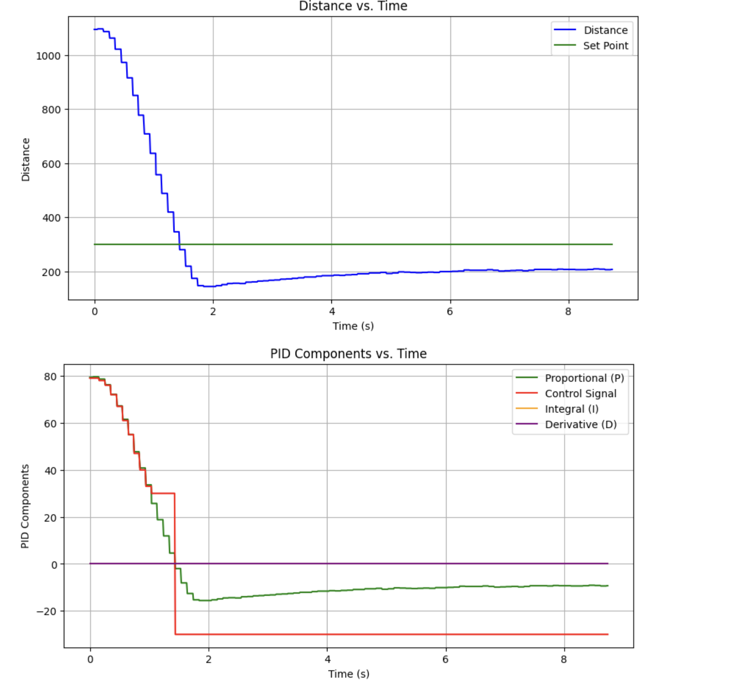
Integral Control
To fix this, I implemented integral control like so:
  // INTEGRAL

  err_i = err_i + err * pid_dt;
  u_i = Ki*err_i;
with gains of .1 and 0.00001 for proportional and integral error, respectively.
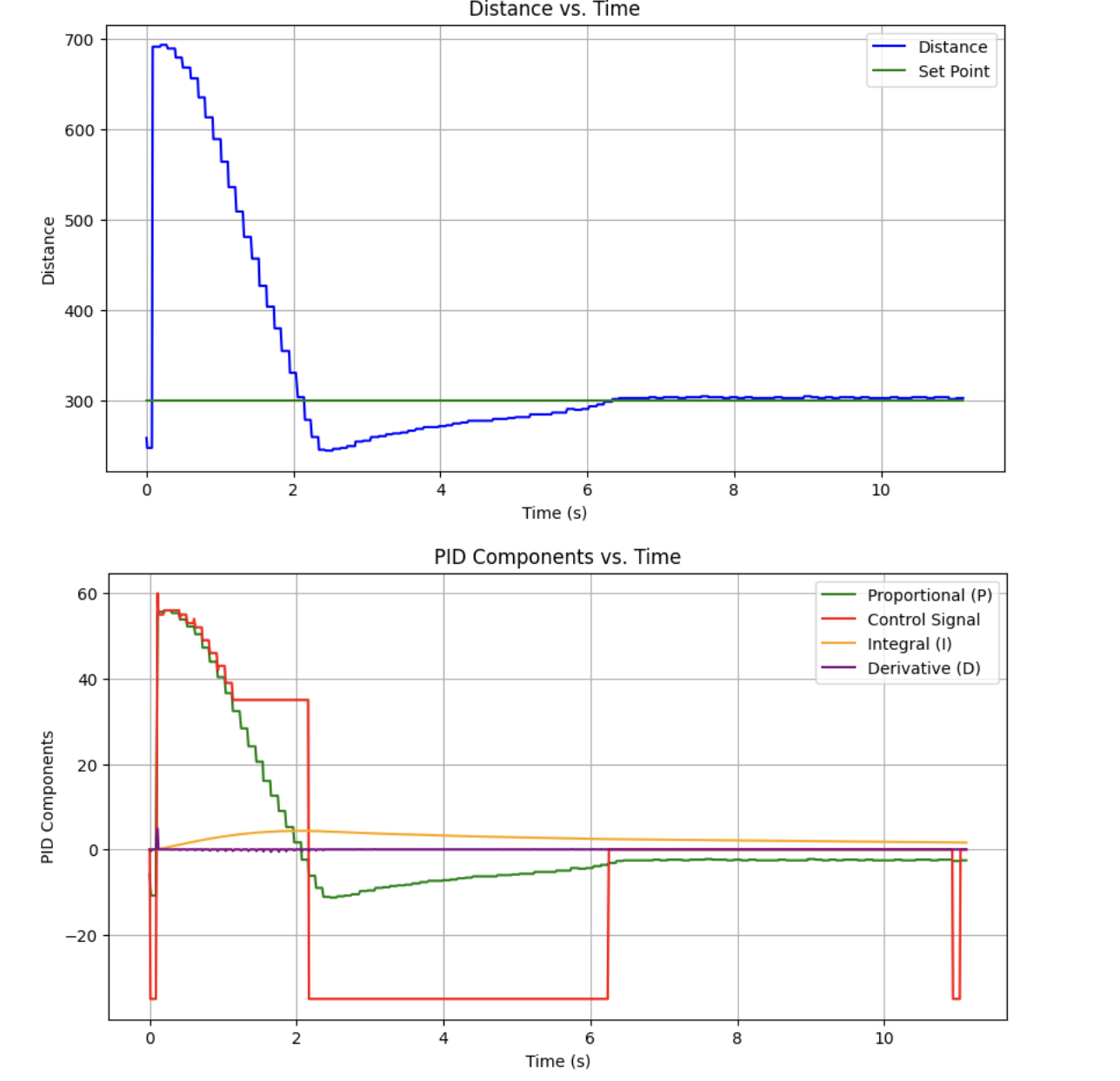
Integral control did its job in reducing steady-state error, and settling time wasn't bad. However, to speed up the system with derivative control, I needed to smooth my TOF measurements in order to avoid serious derivative kick from the small steps in TOF distance.
Frequency/Range
By tracking the changes in TOF data over the course of a few 10-second measurements in long mode, I was able to receieve updated TOF data at around 9.6 Hz, and provide control input at around 75 Hz.
I chose long mode mostly because it would provide more consistent outputs on the scale of an average room. In short mode, I found the sensor to be incredibly noisy (providing values from 1000 to 6000 mm) when out of range, and I suspect that this would cause problems with derivative control.
In open-loop testing, I was able to measure around 990 mm/s as a maximum linear speed, but this may be lower than the truth due to the low battery level I had at the time of testing.
Extrapolation
With the sensor in long mode, I implemented a linear extrapolator. It simply stores the slope between the two most recent TOF measurements (if they exist) and uses that, along with the time interval of the last control loop, to calculate an expected TOF reading.
if (distanceSensor2.checkForDataReady()){
  //Get the result of the measurement from the sensor
  distance2 = distanceSensor2.getDistance();
  distanceSensor2.clearInterrupt();
  recorded_time = millis();

  tof_dt = recorded_time - last_recorded_time;

  if (recorded_c >= 1){
    // we have enough data to extrapolate
    slope = (distance2 - last_recorded_value) / (tof_dt);


  }
  // we don't have enough data to extrapolate
  pid_tof[pid_c] = distance2;
  pid_tof_ext[pid_c] = distance2;
  last_recorded_time = recorded_time;

  last_recorded_value = distance2;


  recorded_c++;

}else{

    // EXTRAPOLATING
    pid_tof[pid_c] = distance2;
    pid_tof_ext[pid_c] = pid_tof_ext[pid_c-1] + slope * (pid_dt);


}
This produced a much nicer response, with better settling time than both previous examples and negligible steady-state error.

Side Note: Extrapolation Debugging
I ran into a lot of trouble with extrapolation over the course of the lab -- the checkForDataReady() function seemed to slow my robot down to an unsustainable degree. I solved this by starting and stopping the ranging of both TOFs in separate BLE commands, and not every loop. After that, careful inspection of my counters led to a successful extrapolation implementation.
Full PID Control
I then implemented derivative control as below, but found its effect to be too noisy.
  // DERIVATIVE
   err_d = - (pid_tof_ext[pid_c] - pid_tof_ext[pid_c-1]) / pid_dt;

   u_d = Kd * err_d_f;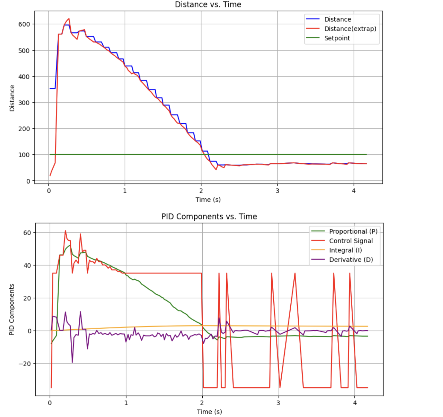
So I implemented a low-pass filter.
  // DERIVATIVE
   err_d = - (err - prev_err) / pid_dt;

  // DERIVATIVE LPF
  alpha_d = .1;
  err_d_f = err_d * alpha_d + (1 - alpha_d) * prev_err_d;
  prev_err_d = err_d_f;

   u_d = Kd * err_d_f;
I performed the following test without motor battery installed:
The derivative gain may have been set too high, but the response also exhibited significant kick due to the step input. To solve this, I calculated my derivative input from the change in distance from the wall instead of error:
err_d = - (pid_tof_ext[pid_c] - pid_tof_ext[pid_c-1]) / pid_dt;
This also didn't solve the issue, though, as the extrapolated distance also ended up stepping from zero.
After tuning the gains over a couple rounds of heuristic 1 (and realizing my derivative gain was reversed):
- Set kp to small value, kd and ki to 0
- Increase kd until oscillation, then decrease by a factor of 2-4
- Increase kp until oscillation or overshoot, decreases by a factor of 2-4
- Increase ki until oscillation or overshoot
- Iterate
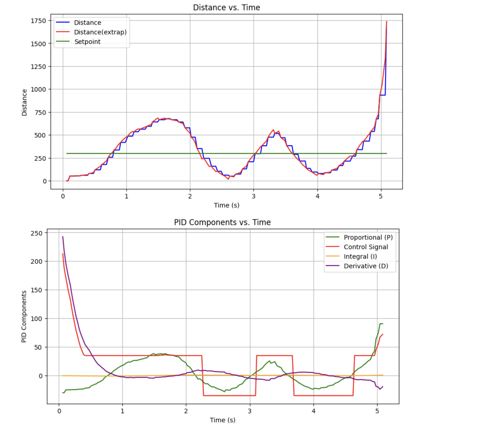
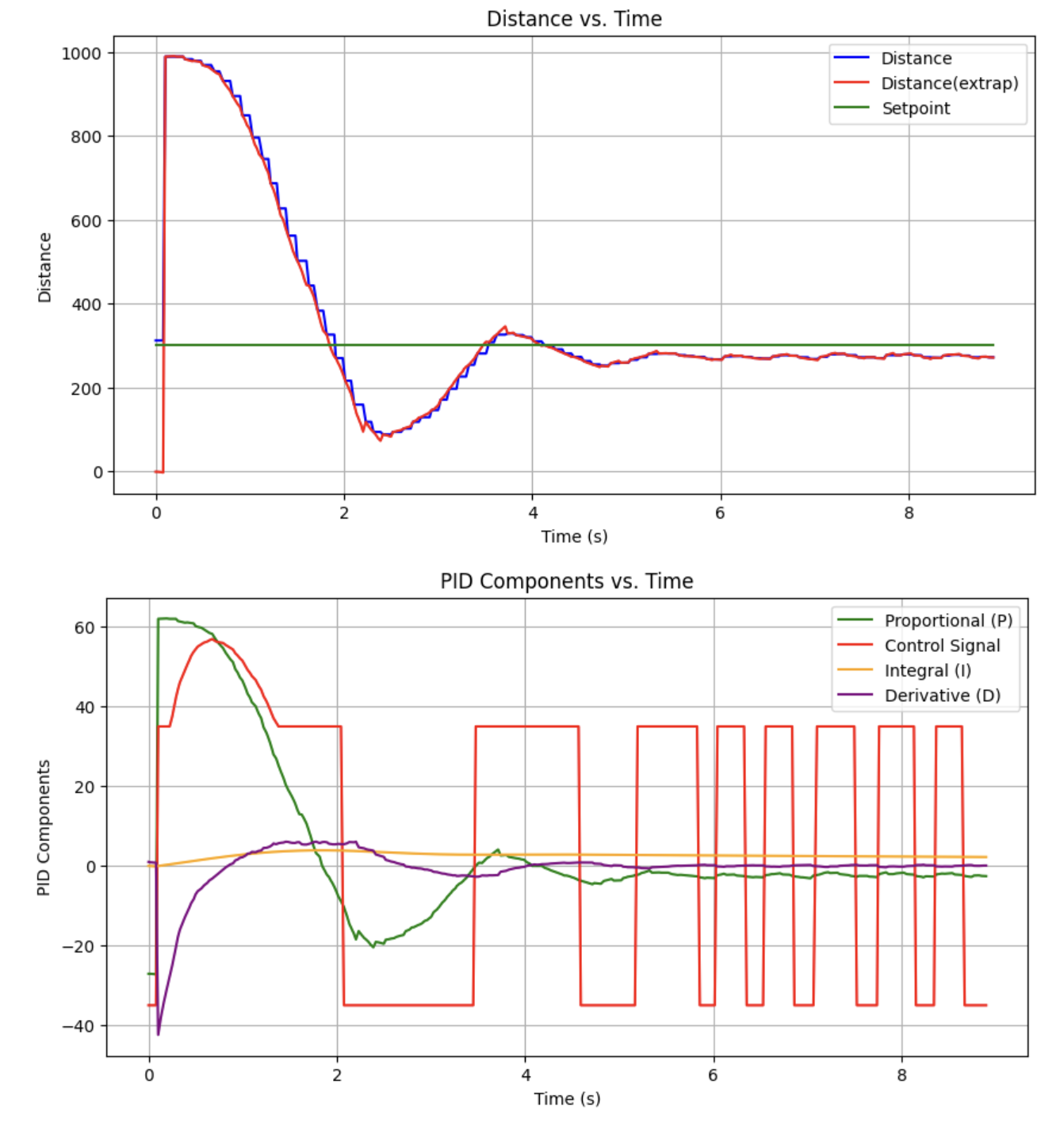
I was able to generate the following response:
I'm satisfied with this for now.
Collaborations
I worked with Lucca Correia and Trevor Dales extensively, and referenced Daria's and Stephan's for code structure and implementation of extrapolation.