Table of Contents
Previous: Lab 5
Setup
To begin implementing orientation control within my current code structure, I added an additional piece of logic in my main loop. This will make controlling both position and orientation at the same time simpler. The dataReady() check is a leftover from previous IMU data recording in Lab 2, and I may have to modify my record_IMU() to use it instead if I run into problems with FIFO overflow issues in the future.
 if (doPID){

  if (doPositionPID){
    record_TOF(2);
    pid_position_tof();
  }
  if ( myICM.dataReady()&&doOrientationPID){
    record_IMU();
    pid_orientation_tof();
  }
  pid_c++;

}
I made slight modifgications to my SET_PID_GAINS and START_PID commands, to accomodate setting separate orientation gains and setpoints. I also added a command SET_PID_TYPE to flag which control(s) should be active upon starting PID.
case SET_PID_TYPE:
  success = robot_cmd.get_next_value(pid_type);
  if (!success) return;
  // success = robot_cmd.get_next_value(recordIGuess);
  // if (!success) return;

  if (pid_type == 1){
    doOrientationPID = 0 ;
    doPositionPID = 1;

  }else if (pid_type == 2){
    doOrientationPID = 1 ;
    doPositionPID = 0;
  }
  else if (pid_type == 2){
    doOrientationPID = 1 ;
    doPositionPID = 1;
  }
  else{
    doOrientationPID = 0 ;
    doPositionPID = 0;
  }

break;
On the client side, my workflow looks like this. It's worth noting that repeatedly sending START_PID with different setpoints allows for changes while control is active:
ble.send_command(CMD.SET_PID_GAINS, "2|1.2|0.00005|10") # 2 = orientation PID, Kp, ki, kd

time.sleep(3); # wait for physical robot setup (start recording, put on ground, etc)

# start PID with recording (true)
ble.send_command(CMD.SET_PID_TYPE, "2") # 1 = position, 2 = orientation, 3 = both
ble.send_command(CMD.START_PID, "600|0|1") # position setpoint, orientation setpoint, record y/n
Recording Yaw Angle
I used the DMP method to record yaw angle, explained step-by-step in Stephan's tutorial on the course site.
It appeared to record data without any issues, as shown in the plot below, where the car was manually turned back and forth.

I manually set the DMP sample rate to 10 Hz, to avoid any issues with FIFO overflow, and the maximum possible speed of 2000 dps is more than sufficient for our purposes. In a open-loop testing, I was never able to get more than three rotations (~1000 degrees) in one second.
Orientation PID Control
To actually implement orientation PID control, I added a separate function within PID.h (see structure) which uses DMP yaw data, along with separate proportional, integral, and derivative gains from position control. operates the same way as PID from lab 5, just with different parameters and a new motor control function, turn().
turn() operates using the spin deadband measured in Lab 4, as well as a higher max speed, to accommodate the higher friction involved in an in-place turn.
float turn (float speed_control){

  float applied_pwm;
  if (speed_control > max_spin) {
    applied_pwm = max_spin;
    spinleft(max_spin);
  }
  if (speed_control < (-1 * max_speed)) {
    spinright(max_spin);
    applied_pwm = -1 * max_speed;
  }
  if (speed_control > 0) {
    if (speed_control > deadband_spin){
      applied_pwm = speed_control;
    }else {
      applied_pwm = deadband_spin;
    }

    spinleft(applied_pwm);

  }
  else if (speed_control < 0) {
    if (speed_control < -1*deadband_spin){
      applied_pwm = -1* speed_control;
      spinright(applied_pwm);
      applied_pwm = speed_control;
    }else {

      applied_pwm = deadband_spin;
      spinright(applied_pwm);
      applied_pwm = -1* deadband_spin;
    }


  }else{
    stop();
    return(0);
  }

  return applied_pwm;

}
My first try went like so, with gains of 2, 0.0005, and 10 for K_p, K_i and K_d respectively:
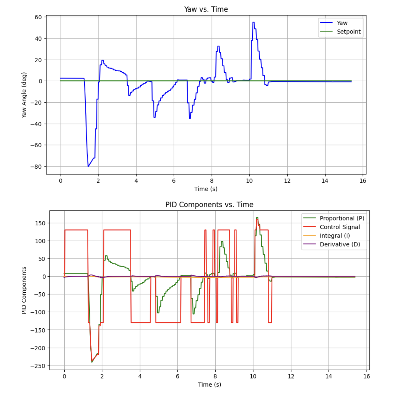
While the corrections looked pretty good after the first second or so, it's worth noting that the robot got significantly off angle initially.
It appeared that the DMP yaw data wasn't updating for the first 1.5 seconds, and unfortunately I wasn't able to figure out why. I had to implement a delay when the control loop initialized in order to prevent the initial overshoot.
With that settled (for now) I then moved on to tuning gains.
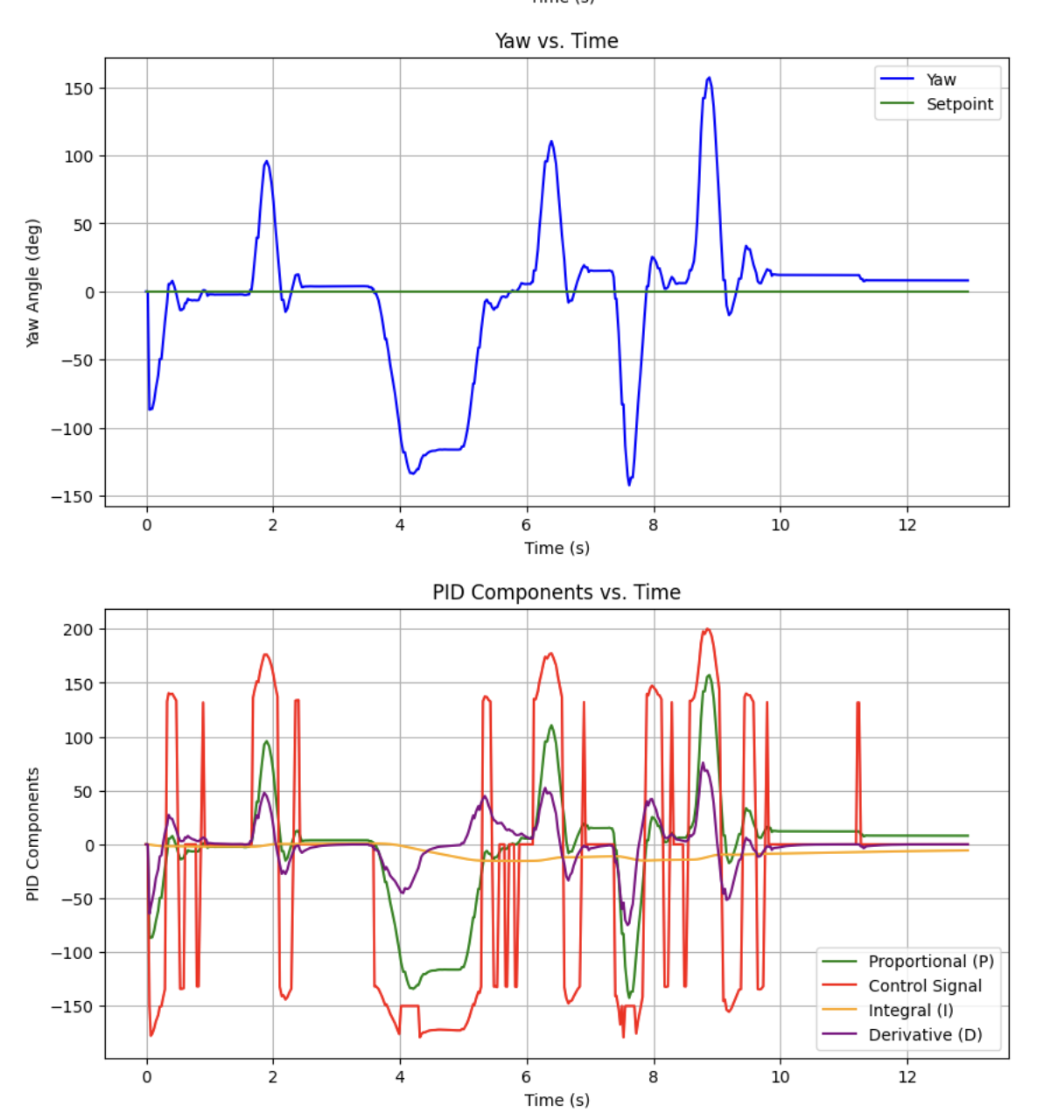
Despite iterating through multiple rounds of heuristic 1, I didn't really find a set of gains that worked better than pure P control. I attribute this to the way I handled my deadband. Instead of clipping low values, it might work better to map the set of reasonable PID outputs onto the interval [deadband_spin, max_spin].
This seemed to work best with [0, 255] approximately mapped onto [135, 250] for the lab floor, using the following formula:
float turn (float speed_control){

  float applied_pwm;

  if (speed_control > max_spin) {
    applied_pwm = max_spin;
    spinleft(max_spin);
  }else
  if (speed_control < (-1 * max_speed)) {
    spinright(max_spin);
    applied_pwm = -1 * max_speed;
  } else
  if (speed_control > 5) {
    // map to valid values

    applied_pwm = .33 * speed_control + deadband_spin;

    spinleft (applied_pwm);


  }
  else if (speed_control < -5) {
    applied_pwm = -0.33 * speed_control + deadband_spin;

    spinright(applied_pwm);

    applied_pwm = -1 * applied_pwm;

  }else{ // input is 0

    // Serial.println("Stopping");
    stop();
    applied_pwm = 0;
  }

  //debug

  return applied_pwm;

}
I tested on a table in another room (after lowering the deadband to accommodate for lower surface friction), and found a lot more success tuning gains with heuristic 1.
Below is one such example, with a better response than both previous.
Derivative Control Considerations
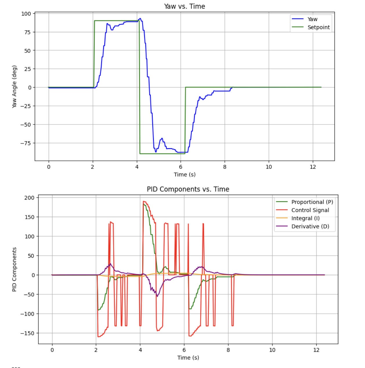
It's worth noting that derivative control of orientation is pretty much a derivative of an integrated signal (as the gyroscope measures angular velocity). However, the onboard DMP process fuses the accelerometer and magnetometer to output yaw. I don't necessarily want to use gyroscope yaw velocity as my derivative error if other sensor data is being taken into account to produce my measurements.
In order to measure the effect of derivative kick, I set the robot to 0, 90, -90, and 0 in sequence. If the following results are any indication, the controller does a fairly good job of accounting for derivative kick. It also seemed to work well enough without a low pass filter.
Collaborations
I worked with Lucca Correia and Trevor Dales extensively, and referenced Daria's and Stephan's for specific PID orientation control considerations.