Table of Contents
Previous: Lab 8
Lab Tasks
Mapping The World
I decided to implement my mapping procedure within a BLE command case, instead of using flags and mainloop checks as in previous labs. Although this did bloat my main ble_arduino.ino a bit more, it was worth it for ease of implementation.
I used the following command, which loops through a set of angle values (in my case, 0 thru 360 degrees in increments of 15) and applies PID control to reach each distance according to the map interval. I used my previous PID recording arrays and BLE data transfer commands to reduce overhead:
case START_MAP:

    doMap = 1;
    success = robot_cmd.get_next_value(map_interval);
    if (!success) return;
    // start TOF ranging
    distanceSensor1.startRanging();
    distanceSensor2.startRanging();

    target_orientation = 0;
    digitalWrite(blinkPin, HIGH); // visual indicator
    for(int i = 0; i<25; i++){ // 24 steps of 15 degrees in 360 degrees


      start_time_map = millis();
      while(millis() - start_time_map < map_interval){  // approx settling time of 15 deg move

        // manually record TOF
        if (distanceSensor2.checkForDataReady()){
          distance2 = distanceSensor2.getDistance();
          pid_tof[pid_c] = distance2;
        }

        record_IMU(); // store DMP yaw to global var
        pid_orientation_tof(); // do orientation PID with recorded yaw
        apply_pid(); // drives motors according to type of control (pos, ori, or both)

        pid_c++;


      }

      target_orientation = target_orientation + 15; // set up next measurement

    }

    digitalWrite(blinkPin, LOW); // visual indicator

break;
This code ended up working reasonably well, giving me a map of the space which looked accurate at first glance. The robot did have some intermittent issues with skipping PID setpoints, but I was unable to diagnose why. Even so, the map ended up being good enough that I just left it alone.
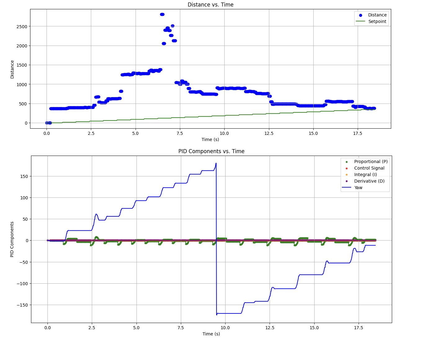
These were the raw TOF and PID control input values (vs time) produced on this run at (5, -3):
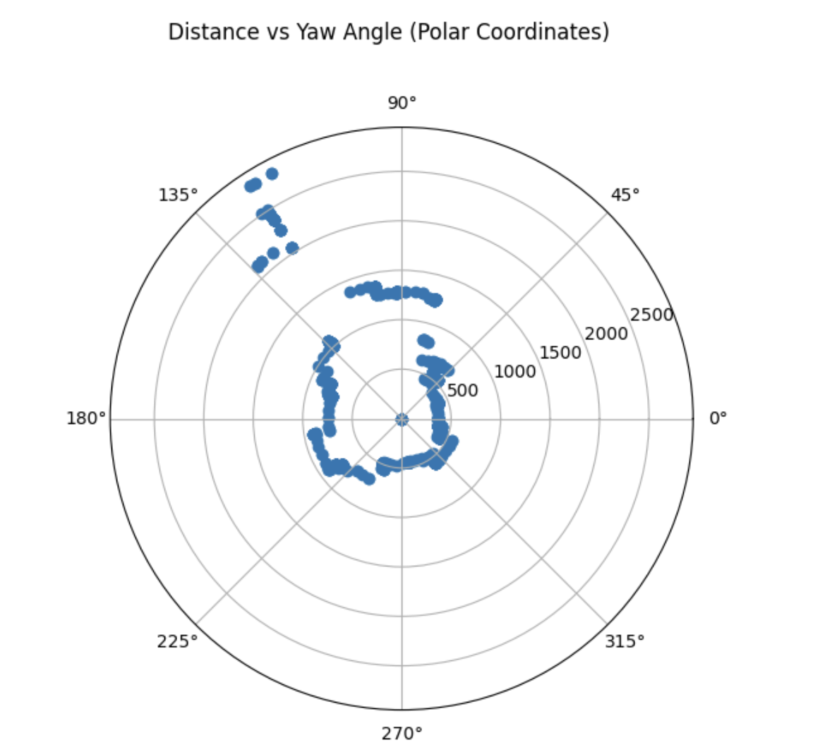
Resulting in this polar distance plot:
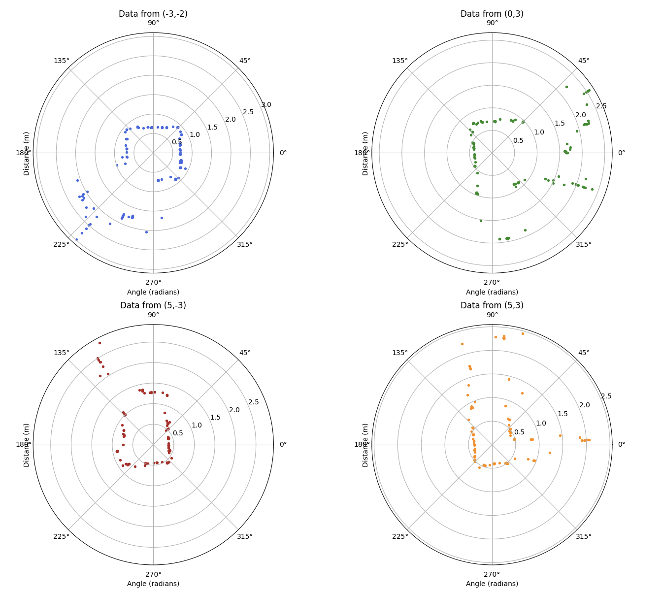
Continuing with these measurements across the space, I was able to get measurements from all four labeled coordinates, as well as the origin:
I then moved on to translating these datasets into global Cartesian coordinates, using the following matrices:
$$ T=\begin{bmatrix}\cos{\theta} & -\sin{\theta} & x \cr \sin{\theta} & \cos{\theta} & y \cr 0 & 0 & 1 \end{bmatrix}
$$
where $x$ and $y$ are the Cartesian coorodinates from the world origin to center of the car and $\theta$ is the measured angle, and an additional offset
$$ P1=\begin{bmatrix}TOF_1 \cr 0\cr 1 \end{bmatrix}
$$
where $TOF_1$ is the distance from the car's center to the front TOF sensor.
I used the recorded orientation values, as I trust the IMU's onboard DMP significantly more than I trust that my robot hit exactly 15 degrees on each rotation. In fact, I'm sure it didn't becasue I saw it skip angles. Regardless, using the DMP yaw angle is clearly the more accurate measureement of the robot's orientation.
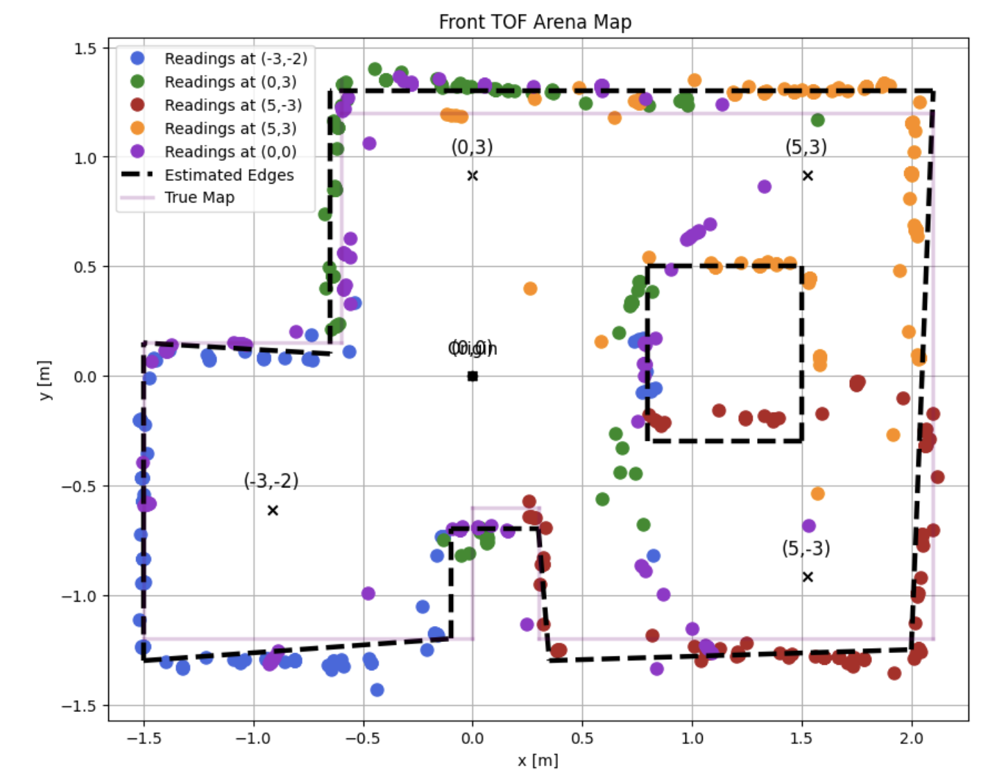
This gave me the following map:
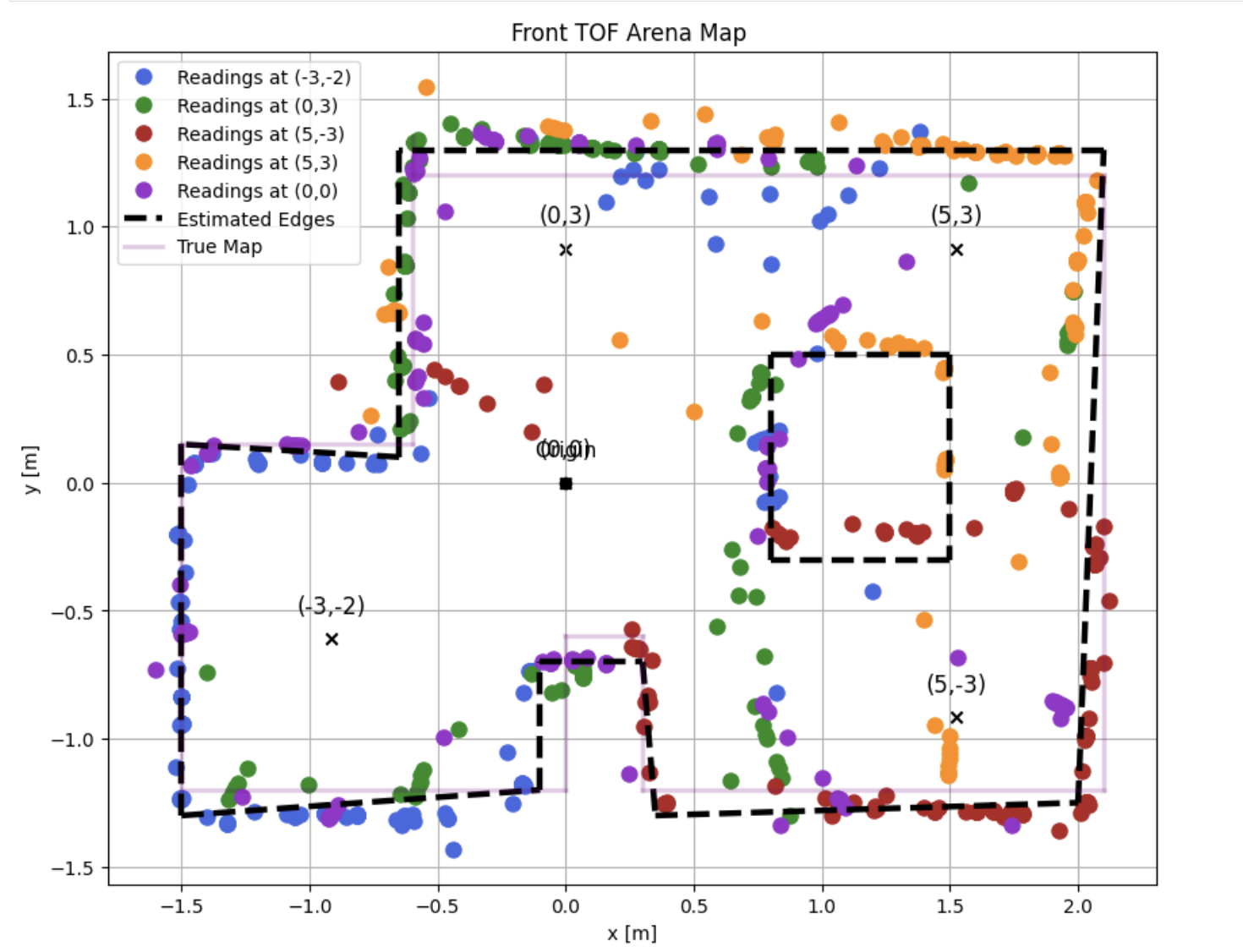
I determined that my TOF wasn't giving accurate reads of the world over ~1.7m, likely due to mounting angle, so I filtered these values out to recalculate the map:
And, to try to further mitigate the noise I was still seeing in the measurements, I resampled. This time, I only took four readings (all labeled points minus origin), and had the robot rotate 720 degrees (i.e., double the loop count in the first code snippet).
This, along with the same distance filter, gave me the following map:
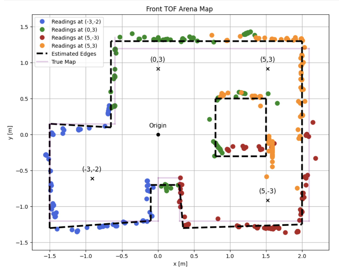
I'm happy with this as an estimate of the world.
Collaborations
I worked with Lucca Correia and Trevor Dales extensively. I used ChatGPT to help with curve fitting and generating nice plots.