Table of Contents
Overview
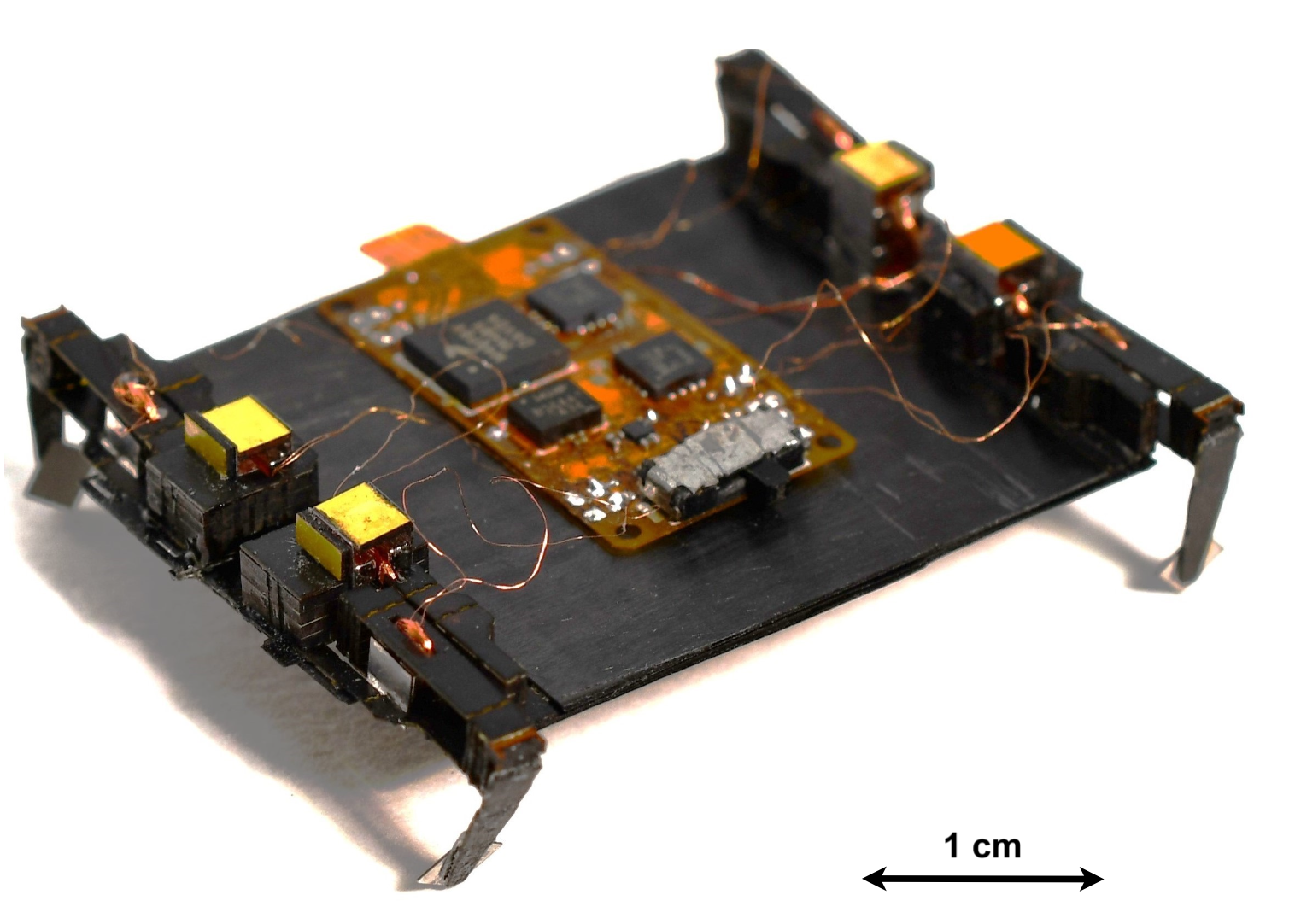
The Cornell MicroTerrestrial (COMT) robot is a 1.5 g electromagnetically actuated quadruped built on PC-MEMS fabrication. Its previous untethered electronics electrically coupled diagonal legs, limiting the system to four independently controlled degrees of freedom (DOFs) out of eight. I designed a replacement flex PCB and embedded control stack that eliminates this coupling, doubles independent actuation authority, and adds onboard sensing for closed-loop heading and range control.
What I built
Flex PCB
The board is a double-sided flexible circuit on 25 µm polyimide dielectric (~120 µm total stackup), bent around the robot's front face to point a time-of-flight (ToF) range sensor forward without a separate bracket. Key design decisions:
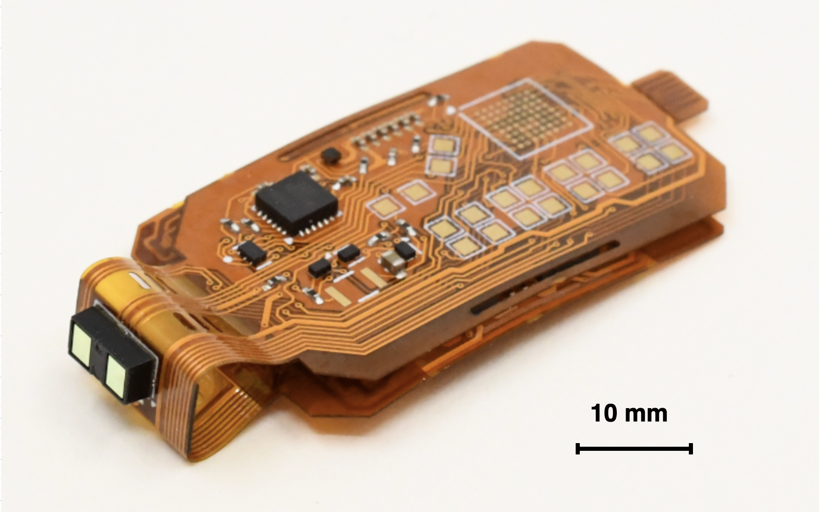
- Independent 8-DOF actuation. Four DRV8833 dual H-bridge drivers replace the previous two, removing the diagonal leg coupling that limited phase control authority.
- Sensor suite. A 9-DOF IMU (ICM-20948) provides magnetometer-aided orientation estimates less susceptible to vibration-induced noise than the previous 6-DOF accelerometer/gyroscope unit. A VL53L1X ToF sensor provides absolute range for position feedback and eventual mapping.
- Mechanical robustness. Staggered trace routing in flexed regions reduces bending stress; all bends exceed the manufacturer's minimum radius (1.44 mm for this stackup). Cut-outs at bend lines reduce the restoring force holding the board flat.
- Signal integrity. Dedicated ground return traces parallel each motor driver output to minimize loop area and inductive coupling, addressing crosstalk issues identified in the prior board. Decoupling capacitors are placed at IC supply pins per IPC-2221A.
Embedded control software
Firmware runs on a Kinetis KL46 (ARM Cortex-M0+, no FPU) and is structured as nested interrupt-driven loops to separate high-rate actuation timing from lower-rate feedback control.
- Actuation layer. A periodic interrupt timer subdivides each gait cycle into 256 phase slices, advancing through a precomputed phasing calendar and updating PWM duty cycles and GPIO direction states for all eight coils with deterministic timing.
- Control layer. A supervisory loop, clocked proportionally to gait frequency, runs two 2-DOF PID controllers in Q16.16 fixed-point: one regulating range (from ToF) and one regulating heading (from fused IMU data). Their outputs combine into per-side duty-cycle commands for current-controlled differential drive.
- Sensor acquisition. ToF and IMU reads are handled by separate interrupt-driven I2C state machines so that blocking peripheral transactions do not stall actuation timing. ToF measurements pass through a fixed-point Kalman filter to interpolate between the sensor's ≤60 Hz update rate and the faster control loop.
- Actuator signal generation. The KL46 has only 12 PWM channels for 16 motor driver inputs. I use a single PWM channel per driver with a low-frequency GPIO gate for direction control, exploiting the DRV8833's shoot-through protection. Measured current asymmetry between fast- and slow-decay modes is ~4%, an acceptable tradeoff for halving PWM channel usage.
Modeling and characterization
Transmission coupling
COMT's legs use two planar four-bar linkages in series (lift and swing), which are not kinematically independent. I measured a 2×2 transmission geometry matrix from high-speed video of single-leg actuation, quantifying the off-diagonal coupling: lift actuation contributes roughly 69% of its tip displacement in the forward (swing) direction. This coupling means both DOFs significantly affect forward speed, and must be accounted for in any model of locomotion performance.
Open-loop speed modeling
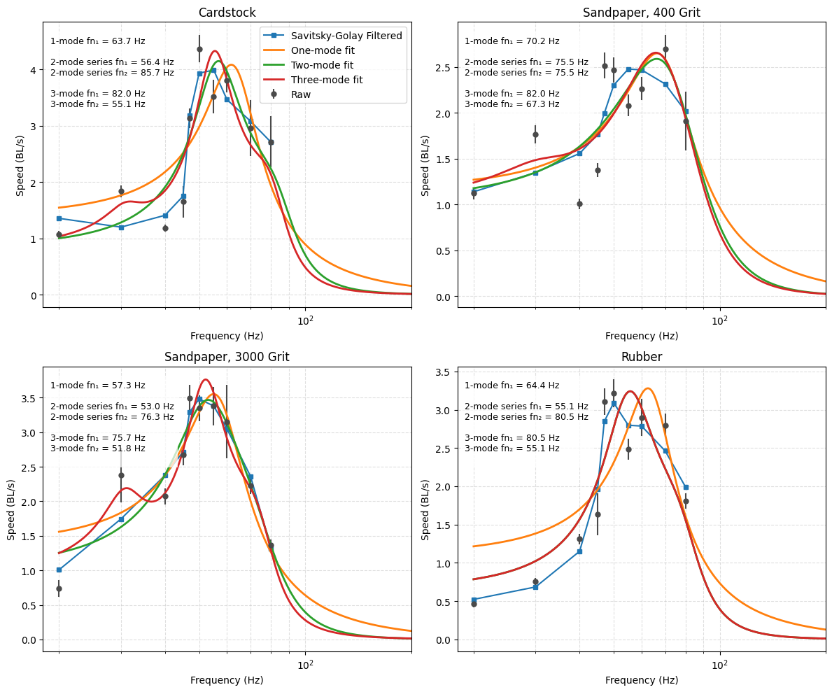
Straight-line speed versus drive frequency exhibits two distinct peaks rather than a single resonance. I fit the data to a cascaded second-order transfer function representing the series lift and swing linkage dynamics. Across four test surfaces, the two-mode model reduced RMSE by 30–50% relative to a single-mode fit, with improved AIC/BIC despite the additional parameter. The identified peaks (~53 Hz and ~85 Hz) do not correspond to the free-vibration modes of the linkages (~125 Hz and ~250 Hz from ringdown tests), suggesting that ground contact shifts the effective resonant structure substantially.
Status
Demonstrated: variable-displacement current control of individual legs via PWM, a complete onboard sensing-to-actuation pipeline running in real time, and open-loop locomotion at up to ~4 BL/s. Not yet tested: closed-loop trajectory tracking on the assembled untethered system (pending actuator manufacturing).
My role
I designed the electronics architecture, PCB layout, and all embedded software. Mechanical design of the chassis, legs, and voice coil actuators was led by Julie Villamil (ECE Ph.D. candidate). Multibody simulations referenced in the modeling sections were primarily developed by Julie Villamil and Cameron Urban.
Full report
This work was completed as my Cornell MAE senior design project. Read the full report here.